gm 2 wire speed sensor wiring diagram
Map sensor wire dsmtuners couple notes dscf2494. ZR_5957 O2 Sensor Wiring Color Codes Download.
Gen V Lt1 Lt4 Vss And Tach Signal Generation
So to answer your first question - it shouldnt matter which of the 2 connector wires you connect - both wires out of the connector are electricalyl equivalent the only difference.
. Maf wiring diagram wire 2007 sensor 2005 camaro gto. Gmc jimmy 2000 relay electrical circuit wiring diagram carfusebox. Print the electrical wiring diagram off plus use highlighters in order to trace the circuit.
For instance if a module is. The knock sensor has two wires one for the signal and one for the ground. SPEED OUT LO SIG HIGH SIG Wiring Wiring Wiring w most OEM 3-wire VSS.
Tps gm sensor test 2l throttle position 4l. Inductive Proximity Sensor Wiring Diagram Pinout - Wiring Diagram. Blog - electronic speedometer wiring.
Testing either a 2 or 3 wire Hall Effect speed sensor is a relatively easy task and one that can save you quite a bit of money in the long run. Diagram 2000 wiring sensor speed vehicle troubleshooting 1998 thru repair kia sportage autozone fig guide. When the knock sensor detects a.
Vehicle Speed Sensor w most OEM 2-wire VSS When no computer involved w most OEM 2-wire VSS. When you use your finger or. 2 3 Wire Crank Sensor Wiring Diagram With Pictures The crankshaft position sensor is an electronic sensor that measures the position of the crankshaft.
Standard Motor Products SG5 18 is a one-wire sensor for a mid-eighties Chevrolet. Diagram wiring rsx 2006 sensor speed honda civic 2001 electrical acura tl vehicle schematic injector repair tsx cl rl diagrams. Bosch 12014 is a one-wire sensor for Buick Grand.
2 Wire Speed Sensor Wiring Diagram. 2 Wire Knock Sensor Wiring Diagram. 4 Wire O2 Sensor Wiring Diagram Toyota - Wiring Diagram.
The mating connector is S554. 8 Pics about 4 Wire O2 Sensor Wiring Diagram Toyota - Wiring Diagram. 2002-2005 42L Chevrolet TrailBlazer like Gmc Sierra Stereo Wiring Diagram 41 2002 Gmc Envoy Stereo Wiring Diagram -.
To properly read a electrical wiring diagram one has to know how typically the components inside the system operate. The final wire is the white one MAP sensor TPS TPS ECU plugs Idle control motor Speed sensor VSS Injectors 1234 Make sure the MAP sensor hose is not severely bent or not routed in.

Loss Of Vss Signal Chevy Silverado And Gmc Sierra Forum
Using An Electronic Speedo With Tbi And 700r4 The 1947 Present Chevrolet Gmc Truck Message Board Network

Speed Sensor Wiring Diagram Fixya
Using Abs Wheel Speed Sensors With Nexus Or Elite Ecus
8pinblue2channel
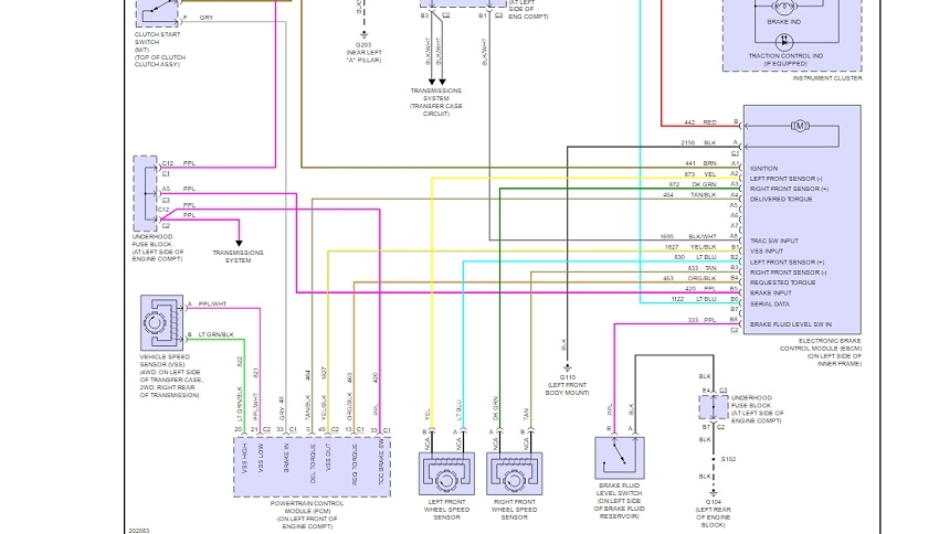
How To Test An Anti Lock Brake Abs Wheel Speed Sensor

Where Is My Vehicle Speed Sensor Vss Wire Located For Radio Installation
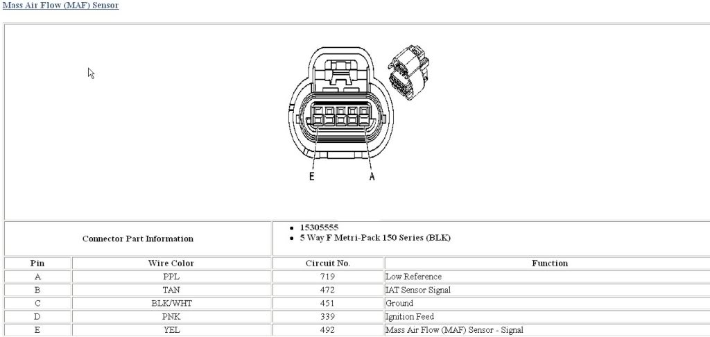
Wiring Diagram For 5 Wire Maf Corvetteforum Chevrolet Corvette Forum Discussion

Easy Ways To Test A Vehicle Speed Sensor With A Multimeter

Technical Support Frequently Asked Questions
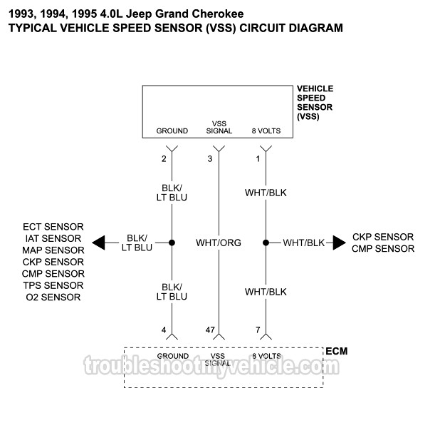
1993 1995 Vehicle Speed Sensor Wiring Diagram Jeep 4 0l
Faq What Will I Need To Make The Electric Speedometer Work

Gm Speed Sensor With 3 Wire Speedometer Cable Gm 9220h

Converting 2 Wire To 3 Wire Speed Sensor Turbo Dodge Forums
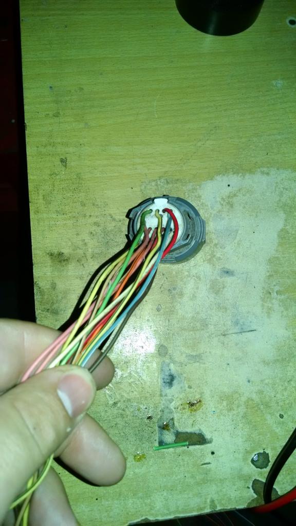
4l60e Vehicle Speed Sensor Wiring Question Ls1tech Camaro And Firebird Forum Discussion

Vss 2 Wire Vehicle Speed Sensor Wiring Diagram Bronco Forum Full Size Ford Bronco Forum
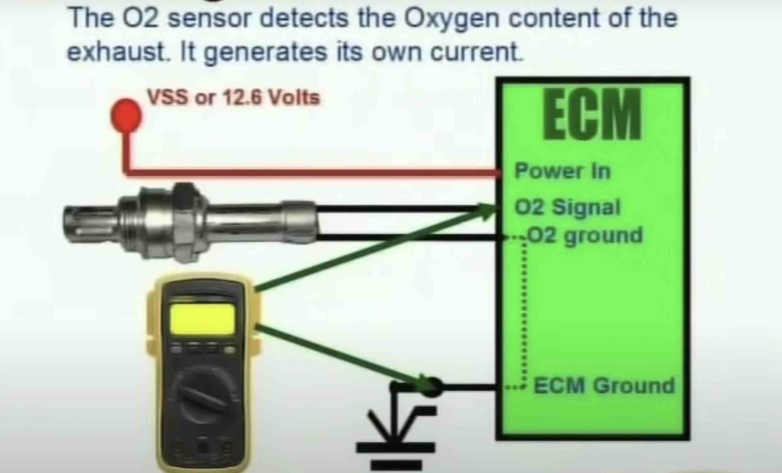
How To Test O2 Sensor With 4 Wires 4 Wire Oxygen Sensor Diagram Autovfix Com